Blind Hole Measurement with an Internal Micrometer

Short answer: you can measure a blind hole with an internal micrometer only when the exact measuring head can reach the required depth and all contacts can sit on the intended cylindrical surface. Clean the bore and contacts, set the instrument against the correct reference, control depth and orientation, avoid the bottom edge and shoulder, then repeat the reading. If the head cannot seat fully, use another method rather than forcing a result.
A blind hole has a closed end, so the last part of the bore introduces features that a through hole does not: a bottom corner, a radius or relief, perhaps a tapered drill point, and often a shoulder or chamfer. The number on the micrometer is useful only if you know which surface produced it. For a garage restorer or small-workshop user, that makes access and contact geometry just as important as nominal diameter.
First decide what part of the blind hole matters
Do not begin by inserting the tool. Begin with the drawing, component information or the fit you are investigating. Record the nominal diameter, the depth band that matters and any feature near that band. A bearing seat near the mouth of a recess is a different job from checking a deep continuous bore. If the decision concerns a particular fitted component, the required measurement position should come from the relevant technical information rather than an improvised universal distance from the bottom.
Inspect the entry chamfer, cross-holes, grooves, damage and visible taper. The surface must be continuous enough for the contacts to seat as intended. If one contact lands in a port while the others touch the bore, the reading does not represent the same geometry as three contacts on the cylindrical surface.
Blind-hole features that can corrupt a reading
| Feature | Risk | Response |
|---|---|---|
| Entry chamfer | A contact may sit partly on the taper and give a misleading size. | Measure below the chamfer with all contacts on the cylindrical surface. |
| Bottom corner or radius | The measuring head may touch an edge rather than the bore wall. | Keep the contacts above the transition and verify full seating. |
| Drill point or conical bottom | The tool may bottom centrally before the contacts reach the required depth. | Check actual head clearance; use another method if access is insufficient. |
| Shoulder or counterbore | Contacts may bridge two diameters or sit on a step. | Identify the exact diameter band and control insertion depth. |
| Port or groove | One or more contacts may lose the intended surface. | Choose a valid orientation and record it, or change method. |
| Burr, swarf or trapped oil | Contamination creates false contact and unstable readings. | Clean and inspect without altering the finished surface. |
Confirm that the instrument can physically do the job
The measuring range tells you only the diameters the instrument is intended to cover. It does not tell you the head length, minimum distance from the bottom, shoulder clearance or ability to pass an entry restriction. Those dimensions must be confirmed for the exact instrument.
- Check that the full expected diameter lies within the stated range.
- Compare the head diameter with the smallest entry on the route into the hole.
- Check contact length and the distance between the contacts and the end of the head.
- Confirm whether the product is designed for blind holes and at what depth.
- Do not assume an extension changes bottom clearance; it may change reach only.
- Make sure the tool can be inserted and withdrawn without scraping the contacts.
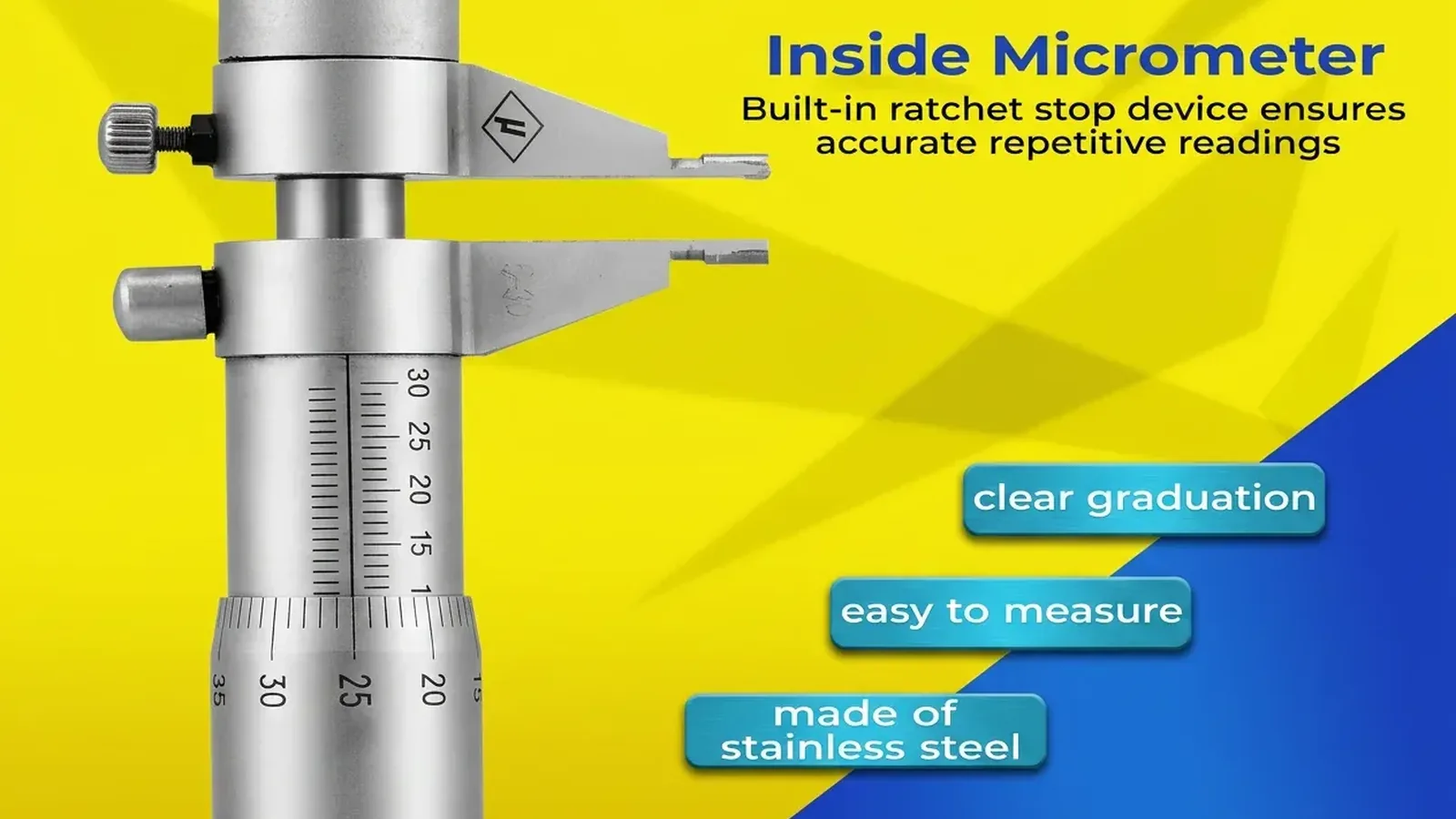
The supported GAROSA facts confirm a 5-30 mm three-point internal/bore micrometer. They do not state its head depth, bottom clearance, shoulder clearance or compatibility with every blind hole. Inspect the actual product information and your component before treating it as suitable.
Prepare the bore, tool and reference
Cleanliness is essential because a small chip or film can become the contact point. Remove loose swarf, oil and debris with a method suitable for the component. Do not polish, stone or deburr a finished measuring surface unless the job specifically authorises that work; changing the surface to make it easier to measure defeats the purpose.
Inspect the micrometer contacts for dirt, damage or corrosion. Let the instrument, reference and workpiece reach stable, similar conditions. A recently machined part should cool before final measurement. Set or check the reference point using the procedure and suitable reference specified for the exact instrument. A reference check is not the same as a full calibration, and the reviewed GAROSA facts do not confirm that a setting ring is included.
If you need a reminder on the reading sequence, use the UK micrometer reading guide before working inside a restricted feature. Practising on an accessible reference is much easier than learning while the head is hidden in a valuable component.
A controlled blind-hole measurement sequence
- Mark the target depth. Use the component requirement to define where the diameter must be assessed. If the tool provides a legitimate depth reference, use it consistently; otherwise create a separate, non-damaging positioning method.
- Retract the contacts for entry. Follow the instrument instructions. Do not drag expanded contacts over the chamfer or force the head past a restriction.
- Insert squarely. Keep the head aligned with the hole and stop at the planned depth. Avoid using the bottom as a crude depth stop unless the instrument is specifically designed for that contact.
- Expand with controlled force. Operate the force-control mechanism as instructed. More force does not make a doubtful reading more true.
- Confirm contact position. Check that every contact is on the intended cylindrical surface, not a groove, port, chamfer, shoulder or edge.
- Take and record the reading. Note depth, orientation and any unusual feel. Withdraw carefully.
- Repeat independently. Reset and reinsert rather than merely reading the same seating twice. A useful repeat checks the whole placement process.
- Compare planned positions. If the job requires several depths, use the same order and method. Do not turn those readings into a pass or fail until compared with the correct specification.
What a suspicious reading feels like
Stop if the tool rocks unusually, becomes tight before the target depth, produces a sudden step as the contacts expand, or repeats only when held against one side. Those signs may indicate edge contact, contamination, misalignment or an interrupted surface. Remove the tool, inspect and rethink the setup. Never increase force to overcome an uncertain seating.
Three-point contact can help alignment in a suitable bore, but it cannot make incompatible geometry disappear. A smooth, repeatable number may still come from the wrong surface. Depth and contact notes are therefore part of the result, not optional workshop paperwork.
When to choose another method
Use another method when the head cannot reach, the required position is too close to a bottom transition, the surface is interrupted, the wall is easily distorted or the decision concerns roundness or cylindricity rather than diameter alone. A suitable bore gauge, plug gauge, coordinate measurement or specialist inspection may be more appropriate depending on the requirement. The right alternative is the one with demonstrated fitness for that task.
For expensive engine or machine work, involve the responsible machine shop before machining if your home measurement conflicts with its process. Sharing a clear record of depth, orientation and conditions is more useful than presenting one unexplained number.
FAQ
Can the contacts touch the bottom of a blind hole?
Only if the instrument is designed for that geometry and its instructions permit it. In many cases, bottom or edge contact can prevent the contacts from seating on the intended diameter. Verify the exact head design and required clearance.
How close to the bottom can I measure?
There is no universal distance. It depends on the head, contact arrangement, bottom radius or taper and the feature being measured. Use dimensions for the exact instrument and component; do not estimate clearance from a product photograph.
Will a three-point micrometer centre itself in a blind hole?
Three-point contact can help alignment in a compatible circular bore, but it cannot correct for a contact resting on a chamfer, port, shoulder or bottom edge. You still need controlled insertion depth and full surface contact.
Should I take the largest of several readings?
Not as a universal rule. Record each reading with its position and use the method specified for the job. Selecting only the largest or smallest number can hide poor seating or an uncontrolled process.
Can I use the GAROSA micrometer for my blind hole?
The confirmed facts establish a three-point format and 5-30 mm range only. Compare your hole with the exact product's head and contact dimensions before deciding. No universal blind-hole compatibility is claimed.
Final workshop advice
A blind-hole reading is credible when the correct contacts reach the correct surface at a known depth under controlled conditions. If any of those points is uncertain, change the setup or the tool. For a compatible bore within 5-30 mm, you can review the GAROSA three-point internal micrometer; confirm access and reference requirements before relying on it for the job.
Sources and further reading
- Mitutoyo Three-Point Internal Micrometer Manual: Reference setting, cleaning, orientation and edge-contact precautions for blind-hole measurement.
- Mitutoyo Borematic Manual: Operational precautions, reference setting and controlled internal measurement.
- NPL Good Practice Guide No. 40: Callipers and Micrometers: Instrument selection, cleanliness, alignment, temperature and internal micrometer use.
- GAROSA product fact card: 5-30 mm range and three-point internal/bore micrometer identity.